


Description
PLEASE NO COPYING FROM OTHER SITES...MUST SHOW WORK IN WORD, NO PICS...PLEASE SEPARATE EACH WEEK IN DIFFERENT DOCUMENT
WEEK 8 LAB
Show work for full credit. Include MultiSIM screenshots where indicated.
- Consider the parallel inductive reactive circuit below. Calculate the following: (Express all answers in magnitude/phase angle form)
- Zeq
- IT
- XL2
- XL1
- IR1
- IR2
- IL1
- IL2
Parallel Inductive Circuit: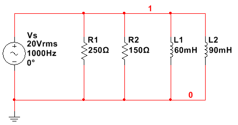
- Consider the series RC circuit below:
- Assume C1 is completely discharged with S1 in the position shown. If S1 is moved to the top position, how long will it take for the capacitor voltage to reach
- 3V
- 6V
- 15V
- 20V
- Assume that C is completely discharged with S1 in the position shown. If S1 is moved to the top position, how much is the resistor voltage at the following time intervals?
- t = 0 s
- t = 4.5 ms
- t = 10 ms
- t = 15 ms
- t = 25 ms
Series RC Circuit: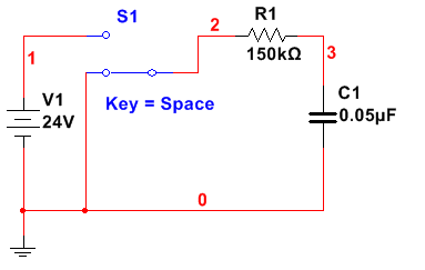
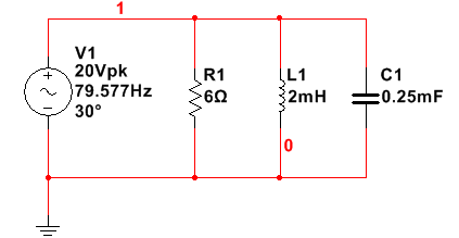
- Analyze the RLC circuit below to determine the following (include both polar and complex forms where applicable):
- Zeq
- IT
- IR1
- IL1
- Real Power (Watts)
- Reactive Power (VARs)
- Apparent Power (VAs)
- Power Factor
- Construct the circuit in MultiSIM and run a Single Frequency Analysis to confirm your calculations for the phasor values in part 3. Capture a screenshot of the analysis for both Magnitude/Phase (polar) and Real/Imaginary (complex).
- Measure the real power of the circuit and the power factor using a watt meter. Capture a screenshot of the watt meter readings.RLC Circuit:
Show work for full credit. Include MultiSIM screenshots where indicated.
- Consider the parallel inductive reactive circuit below. Calculate the following: (Express all answers in magnitude/phase angle form)
- Zeq
- IT
- XL2
- XL1
- IR1
- IR2
- IL1
- IL2
- Consider the series RC circuit below:
- Assume C1 is completely discharged with S1 in the position shown. If S1 is moved to the top position, how long will it take for the capacitor voltage to reach
- 3V
- 6V
- 15V
- 20V
- Assume that C is completely discharged with S1 in the position shown. If S1 is moved to the top position, how much is the resistor voltage at the following time intervals?
- t = 0 s
- t = 4.5 ms
- t = 10 ms
- t = 15 ms
- t = 25 ms
- Assume C1 is completely discharged with S1 in the position shown. If S1 is moved to the top position, how long will it take for the capacitor voltage to reach
- Analyze the RLC circuit below to determine the following (include both polar and complex forms where applicable):
- Zeq
- IT
- IR1
- IL1
- Real Power (Watts)
- Reactive Power (VARs)
- Apparent Power (VAs)
- Power Factor
- Construct the circuit in MultiSIM and run a Single Frequency Analysis to confirm your calculations for the phasor values in part 3. Capture a screenshot of the analysis for both Magnitude/Phase (polar) and Real/Imaginary (complex).
- Measure the real power of the circuit and the power factor using a watt meter. Capture a screenshot of the watt meter readings.RLC Circuit:
WEEK 7 LAB
Series and Parallel Inductive Reactive Circuits in Complex Form
WEEK 6 LAB
Series L/R and RC Circuits
- Watch the video....WILL PROVIDE LOGIN TO VIEW VIDEO
- Week 6 Video Lecture – Multisim Series RL
- Construct the series L/R and RC circuits from this week’s assignment in MultiSIM and perform Transient Analysis on each circuit to confirm your calculations. Use a 5% tolerance for all of the components. Capture a screenshot of the output of the analysis to confirm your calculations. Create a table to demonstrate your expected and measured values.
- Include a discussion of the following:
- Differences between the calculations and the simulations.
- How would you go about designing a circuit with an applied voltage of 24V and a resistor of 1kohms such that the current in the circuit starts out at 0A and reaches 24mA in 2 seconds?
- How would you go about designing a circuit with an applied voltage of 24V and a resistor of 1kohms such that voltage starts out at 0V and reaches 24V in 2 seconds?

User generated content is uploaded by users for the purposes of learning and should be used following Studypool's honor code & terms of service.
Explanation & Answer

Attached.
1
Running Head: ENGINEERING QUESTION
Engineering ...
Review
Review

Anonymous
Just the thing I needed, saved me a lot of time.
Studypool

4.7
Trustpilot

4.5
Sitejabber

4.4


Similar Content
Abubakar Tafawa Balewa University Fouriers Law Equation Questions
hi i need you to answer all questions Why is there a minus sign in Fourier’s law equation?What is an isotropic material?...
American University of Technology Measurement of Humidity and Temperature Essay
Topic: Humidity Sensorscourse: applied electromagnetics Requirements are the following:IntroductionTheoryapplicationsequat...
Campbellsville University Project Management Process Reflection Paper
Sub:Project management process
Job: Software Engineer
Provide a reflection of at leas...
CE 330 Southern Illinois University Carbondale Lab Report
CE 330 Civil Engineering Materials Lab (Fall 2019)
Tuesday – 2:00 PM to 3:50 PM / Thursday- 9 AM to 10:50 AM
Sandeep Bu...
Hudson County Community College Sustainable Civil Engineering Worksheet
...
Engineering Risk Management
Hello my friendi need you please to take a look in my final exam i need it in details and sources please i need ...
20200213082225infotech Import Strategy New
In our contemporary digital world where everything happens at a fast rate, there are numerous ways through which business ...
Outlien For Infotech And Mobile Applications.....
Thesis; organizations can use mobile apps to improve their capabilities, explore new profitable Smart organizations have l...
Material Production Assignment.edited
Material production involves a complex process that encompasses time scheduling, ordering, forecasting market preferences,...

